CPU part 8 - The first pipeline
Until now, every part of the CPU lived on its own: the ALU, the decoder, the register file, and the forwarding, hazard and branch units. In this post they finally come together into a pipeline that runs actual programs. It can’t access memory yet, but it can already calculate, branch and jump, which is enough to run loops.
One module per stage
The pipeline consists of five stages, so the CPU consists of five stage modules: cpu_if, cpu_id, cpu_ex, cpu_mem and cpu_wb. Each stage module starts with the pipeline register in front of it, followed by the logic of that stage. So cpu_ex starts with the ID/EX register and then has the ALU, and cpu_mem starts with the EX/MEM register. This way, every file reads from top to bottom like what the stage does in a cycle: take over the instruction from the stage before, and then work on it.
The modules from the previous posts are placed inside the stage they belong to. For example, the decoder, the register file and the forwarding unit are all part of cpu_id. The only exception is the hazard unit, as it does not belong to a single stage, but looks at all of them.
This is quite different from my previous CPU designs, where most of the pipeline was in one big file. That made it hard to see which signal belonged to which stage, and in which cycle something happened.
A top level without logic
The top-level module, b32p4, contains no logic at all. It only declares the wires between the stages, and connects the five stage modules and the hazard unit to each other. Besides the clock and reset, the CPU itself only has the port to the instruction memory, and a debug port that shows each instruction as it finishes, which I only use in simulation.
The price of splitting everything up like this is wiring: a signal that goes from ID to EX has to be declared in the top level, and connected to both modules. That is quite a lot of lines of code, but it’s dumb code that is easy to check. The nice thing is that you never have to look for logic in the top level: if something is computed, it is in one of the stages.
What each stage does
Right now, the stages do the following:
| Stage | Starts with | What it does |
|---|---|---|
| IF | the PC | fetches the next instruction |
| ID | the IF/ID register | decodes the instruction, reads the registers, decides where each value will come from, and computes the target of a branch or jump |
| EX | the ID/EX register | picks the forwarded values, runs the ALU, checks the branch condition, and computes the target of a jumpr |
| MEM | the EX/MEM register | redirects the PC for a jump or taken branch |
| WB | the MEM/WB register | writes the result into the register file |
MEM is quite empty for now, as memory access is what comes next.
IF is the only stage that is not built around one of the units from the previous posts, so it is worth a closer look. The instruction memory is a block RAM outside the CPU, which, as explained in the register file post, only gives its data one clock edge after it got the address. So IF gives the memory the address of the next instruction, and at the clock edge, the memory and the PC both take it:
assign fetch_addr = reset    ? ROM_BASE :
                    redirect ? redirect_target :
                               pc + 32'd4;
assign fetch_en   = reset || redirect || !stall_if;

always @(posedge clk)
    if (fetch_en)
        pc <= fetch_addr;
This way, the word that comes out of the memory is always the instruction at the PC. After a reset, the CPU starts at the beginning of the ROM, and a redirect goes before a stall, just like in the hazard unit. When IF stalls, the memory does not take a new address, so it simply keeps giving the same instruction.
Valid bits
Every pipeline register has a valid bit, which says whether there is an actual instruction in it. This is where the stall and flush signals from the hazard unit end up. A stalled register keeps everything it has. A flushed register only clears its valid bit: the rest keeps whatever was in it, because an instruction without the valid bit is ignored anyway.
For this to work, everything that does something, like writing a register or redirecting the PC, is combined with the valid bit of its stage. That way, a bubble can never do anything, no matter what garbage is left in the rest of its pipeline register. A nice side effect is that the reset only has to clear the valid bits, and not the whole pipeline register. All of this means that a reset, stall or flush only needs one bit per stage, instead of a lot of logic on every bit of every pipeline register.
The pipeline at work
Here is the demo program I use to show the whole pipeline:
load 1 r1
load 2 r2
add r1 r2 r3        ; r2 from MEM, r1 from WB
xor r3 r1 r4        ; r3 from MEM
bne r4 r0 End       ; r4 from MEM, taken
add r0 1 r5         ; flushed
add r0 2 r6         ; flushed
add r0 3 r7         ; flushed
End:
halt
cycle 0 1 2 3 4 5 6 7 8 9 10 11 12
load 1 r1 IF ID EX MEM WB
load 2 r2 IF ID EX MEM WB
add r1 r2 r3 IF ID EX MEM WB
xor r3 r1 r4 IF ID EX MEM WB
bne r4 r0 End IF ID EX MEM WB
add r0 1 r5 IF ID EX ✗
add r0 2 r6 IF ID ✗
add r0 3 r7 IF ✗
halt IF ID EX MEM WBThe add needs r2 from the instruction right in front of it, and r1 from the one before that. Both are forwarded, so it doesn’t have to wait, and the same goes for the xor and the bne. The bne reaches MEM in cycle 7, and redirects the PC to End. The three add instructions behind it are flushed, so they never write their registers, and the halt is fetched in cycle 8.
Simulation
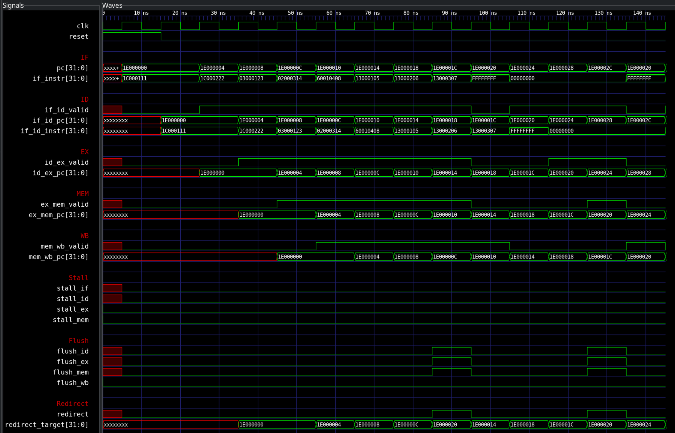
Here you can see the demo program in GTKWave. Each stage gets its own section, with the valid bit and the PC of the instruction that is in it, so you can follow an instruction through the pipeline by following its PC diagonally down. Some things to look at:
- After the reset, the valid bits become 1 one stage at a time, as the first instruction moves through the pipeline.
- In cycle 7,
redirectis 1 while thebneis in MEM, and the flush signals of ID, EX and MEM are 1 at the same time. In the next cycle, the valid bits of those three stages are 0, and the PC is atEnd. - The pipeline does not know that
haltis special, so it fetches the instructions after it as well. In cycle 11 thehaltis in MEM, and redirects to itself, which flushes those again, just like thebnedid. The simulation stops once thehalthas finished. - None of the stall signals is ever 1: nothing in this pipeline has to wait yet.
Next steps
Next is memory: reading and writing data. That brings the first results that come too late to forward, and with that the first real stalls.