CPU part 13 - Interrupts
Programs often have to react to things that happen outside the CPU, like a key being pressed, a byte arriving at the UART or a timer running out. A program can keep checking for these itself, but the devices can also ask for the attention of the CPU when they need it. That is what interrupts are for. In this post I explain how interrupts work, what the options are, and how they ended up in the B32P4 CPU.
Why interrupts
Without interrupts, a program has to check each device itself, over and over again. This is called polling:
Loop:
    read 0 r10 r1       ; is there a byte at the UART?
    bne r1 r0 HandleByte
    ...                 ; the rest of the program
    jump Loop
Polling is simple, and for a small program it works fine. But it wastes time on checks that are almost always negative, and the program reacts only as fast as it gets around to the check. A byte that arrives while the program is busy with something else for a while can even get lost, if the device has no room to keep it.
With interrupts, the device tells the CPU itself. The CPU then stops what it is doing, runs a piece of code for that device (the interrupt handler), and afterwards continues where it was, as if nothing happened. The program itself does not have to check anything.
I would say having interrupts is a must for writing non-trivial programs, as without them you can never do longer calculations without baking in polling checks all over your code base.
The FPGC has several interrupt inputs for things like IO triggers (e.g. UART byte received), hardware timers, or even notifications from the GPU like when a frame has been drawn (for synchronization between CPU and GPU).
How a CPU takes an interrupt
To take an interrupt, the CPU (in our case, as other CPUs might do this slightly differently) has to do a few things:
- Decide where in the program it stops.
- Remember where to continue afterwards.
- Jump to the interrupt handler.
- Find out which device it was.
- Continue the program at the end of the handler.
The handler then has to make sure the program does not notice anything, so it saves the registers it uses at the start, and puts them back at the end.
Where to stop
The first step is the hardest in a pipelined CPU. At any moment there could be five instructions in the pipeline, in different stages. If the interrupt is taken “between two instructions”, then all instructions before that point have to finish, and all instructions after it must not have changed anything.
| Option | How | Pros | Cons |
|---|---|---|---|
| At any instruction | the CPU picks an instruction, lets all older ones finish, cancels it and everything behind it, and saves its address | reacts within a few cycles, no matter what the program does | any instruction in any stage must be cancellable, also halfway through a multi-cycle instruction like a divide |
| Only at certain instructions | the CPU only stops at instructions where it is easy, for example at jumps | very little hardware | the time to react depends on the program: a long piece of code without jumps delays the interrupt |
Almost all real CPUs, like x86, ARM and RISC-V, take interrupts at any instruction. They need to be able to stop at any instruction anyway, for things like virtual memory, where an instruction can fail halfway and must be run again after the operating system fixed the problem. For that, every stage of the pipeline must be able to cancel its instruction, and the CPU must know exactly which instructions already changed something. Also for very timing critical programs like you might run on microcontrollers, the latency after an interrupt must be predictable and as short as possible.
Which device it was
There are roughly two ways a CPU can find the right handler:
- One handler for everything. The CPU always jumps to the same address, and the handler reads which interrupt it was from a register. RISC-V works this way in its basic mode.
- A handler per interrupt. The CPU looks up the address of the handler in a table, with one entry per interrupt (a vector table). ARM Cortex-M microcontrollers work this way.
Some CPUs can also take an interrupt during the handler of another one, when the new one is more important. This is called nesting. ARM Cortex-M can do that, and it even saves a few registers on the stack by itself before jumping to the handler. That makes interrupts fast and easy to use from C, but it is also a lot of extra hardware.
What is in B32P4
For now I kept the interrupt model of the previous FPGC versions, and in the previous FPGC versions interrupts have always been a bit of an afterthought. So unsurprisingly, it is kept as simple as possible while allowing everything I really need in the software I run on the FPGC. I decided not to improve on this part of the B32P4, as it adds complexity without me probably using the advantages it brings. So for now, the B32P4 does the following for handling interrupts:
- Only at jumps. An interrupt is only taken instead of a jump, a
jumpr, a taken branch or ahalt. When I look at the assembly output of compiled C programs, I almost never see longer sequences of instructions without branch or jump. - Only in SDRAM. Code in ROM is never interrupted, so the bootloader can do its work without being disturbed. The primary reason for this is that the interrupt vector lives in SDRAM, which is uninitialized during the bootloader phase.
- One handler. The CPU always continues at address
0x4, the interrupt vector. The handler reads the number of the interrupt withreadintid, which can then be used in an if or case statement to handle different interrupts. - Only the PC is saved. The address of the interrupted jump goes into
PC_BACKUP. The handler saves any registers it uses itself, preferably usingpushandpopas those do not require new register values as arguments. Implementing a hardware backup is currently not worth the performance gains as interrupts do not happen that often. - No nesting. Interrupts are disabled during the handler. An interrupt that comes in during the handler waits until after
reti. - The lowest number first. When several interrupts are waiting, interrupt 1 goes first, then 2, and so on.
A program in SDRAM then looks a bit like this:
    jump Main           ; address 0: the start of the program
                        ; other fields/program headers
    jump Interrupt      ; address 4: the interrupt vector
Main:
    ...
Interrupt:
    push r1
    push ...
    readintid r1        ; which interrupt was it?
    ...                 ; handle it
    pop ...
    pop r1
    reti                ; back to the jump that was interrupted
reti jumps back to PC_BACKUP and enables interrupts again. The jump that was interrupted then simply runs, as if nothing happened.
Taking interrupts only at jumps is what makes this so cheap in a pipeline. A jump already flushes the instructions behind it, and a jump does not change anything other than the PC. So to take an interrupt, the CPU only has to change where the jump goes: to 0x4 instead of its own target. And instead of continuing at the jump target afterwards, it continues at the jump itself, which then runs again. The cost is that the time to react depends on the program. A long divide or a long piece of code without jumps delays the interrupt. A halt is a jump to itself, so a program that waits for an interrupt with halt can still be interrupted.
Pending interrupts
Before the CPU can take an interrupt, it has to notice it. The devices give a signal that goes from 0 to 1 when they want attention. There are two ways to look at such a signal:
| Option | How it works | Pros | Cons |
|---|---|---|---|
| Level-triggered | the interrupt is there as long as the signal is 1 | nothing gets lost, the device keeps asking until it is handled | the handler must make the device lower its signal, or the interrupt is taken again right after reti |
| Edge-triggered | only the moment the signal goes from 0 to 1 counts | the device only has to give a short pulse, and it does not matter how long that pulse is kept high | the CPU has to remember the interrupt until it takes it |
B32P4 uses edges. For each input, a rising edge sets a pending bit, and that bit stays set until the CPU takes the interrupt. The CPU always takes the lowest pending number. So if interrupts 3, 1 and 2 come at the same time, the CPU first takes 1. Its reti returns to the jump that was interrupted, and 2 is taken right there, instead of that jump. After the handler of 2, the same happens for 3, and only then does the jump itself run. The CPU picks the number when it takes the interrupt, so a lower number that comes in just before that still goes first. An interrupt that comes in while its pending bit is already set is not counted twice. In that case the second interrupt gets dropped, which is by design to prevent infinite loops on too long interrupt handling in combination with very fast incoming interrupts.
Signals from outside the clock domain
Not all interrupt signals come from logic that runs on the same clock as the CPU. The GPU runs on its own clock, and the Ethernet controller chip is not even inside the FPGA. Such a signal can change at any moment, also right at the clock edge of the CPU. A flip-flop needs its input to be stable for a short time around the clock edge. When it changes right then, the flip-flop can end up somewhere between 0 and 1 for a while before it falls to one side. This is called metastability, and if the rest of the logic sees that undecided value, some parts can read it as a 0 and others as a 1 in the same cycle.
For a single bit, the standard solution in an FPGA is a synchronizer: two flip-flops in a row. The first one may go metastable, but it has a whole clock cycle to settle before the second one takes its value, which is almost always enough. Quartus has settings to recognize these chains, so it can place their flip-flops close together and estimate how rarely a metastable value could still get through.
So each interrupt input goes through two flip-flops first, and then through a third one that holds the value of the cycle before. When the second one is 1 and the third one is still 0, that is a rising edge. This means an interrupt becomes pending three cycles after the signal goes high, which does not matter at all compared to the time it takes until the next jump.
About this clock domain issue: handling clock domain crossing is generally quite complex and tricky, especially as it is challenging to simulate. This is the main reason why I try to run every part of the design at the same clock, unless it is completely separated from the rest (like the GPU, which mainly interfaces with the CPU through dual clock BRAM blocks that handle the crossing). Single bits like interrupts are simple though as they only need this small synchronizer.
Interrupts in the pipeline
Deciding in EX
A jump redirects in MEM, but the CPU decides whether to take an interrupt instead while the jump is still in EX. Three things must hold at that moment: an interrupt is pending, interrupts are enabled, and the jump is in SDRAM. The decision then goes along to MEM with the jump, just like the result of the branch compare. In MEM, the CPU then only has to pick the target from registers that are already there, which keeps that part fast.
When the jump leaves MEM, the interrupt is taken:
- the PC continues at
0x4 PC_BACKUPgets the address of the jump- interrupts are disabled
- the number of the interrupt is recorded for
readintid, and its pending bit is cleared
For a taken jump, the pipeline looks exactly the same as without an interrupt. Only the target is different:
cycle             0   1   2   3   4
bne r2 r0 Loop    IF  ID  EX  MEM WB      ; the interrupt is taken instead
halt                  IF  ID  EX          ; flushed
                                  IF      ; the instruction at 0x4
In cycle 2 the bne is in EX, an interrupt is pending, so the CPU decides to take it. In cycle 3 the bne is in MEM, and redirects to 0x4 instead of to Loop. The instructions behind it are flushed, just like after any other taken jump. When the handler is done, its reti returns to the bne, which then runs as if nothing happened.
Why deciding early is safe
Deciding in EX and only acting in MEM a cycle later sounds like it could go wrong: what if something changes in between? Only two things can change whether interrupts are enabled: taking an interrupt and reti. Both are redirects, so they flush the instruction that is in EX at that time:
cycle             0   1   2   3   4
reti              ID  EX  MEM WB          ; enables interrupts at the end of cycle 2
jump Loop             ID  EX              ; flushed by the reti in cycle 2
The jump Loop behind the reti decides in cycle 2, while interrupts are still disabled, but the reti flushes it in the same cycle. The instruction that really comes next is the one at PC_BACKUP, and that one decides when interrupts are already enabled again. A pending interrupt also cannot disappear in between, as only taking it clears it. So a decision made in EX still holds when the jump is in MEM.
Returning
reti reads PC_BACKUP in MEM, just like the CPU-internal registers. At that point all older instructions are done, so a handler can write a different return address to PC_BACKUP right before reti, and reti will use it:
Interrupt:
    load32 0x1F000000 r2
    addr2reg Elsewhere r3
    write 0 r2 r3       ; PC_BACKUP
    reti                ; continues at Elsewhere
This is what an operating system needs to switch between tasks: save the return address of one task, and return to another one.
Simulation
Let’s look at the interrupt controller in a simulation.
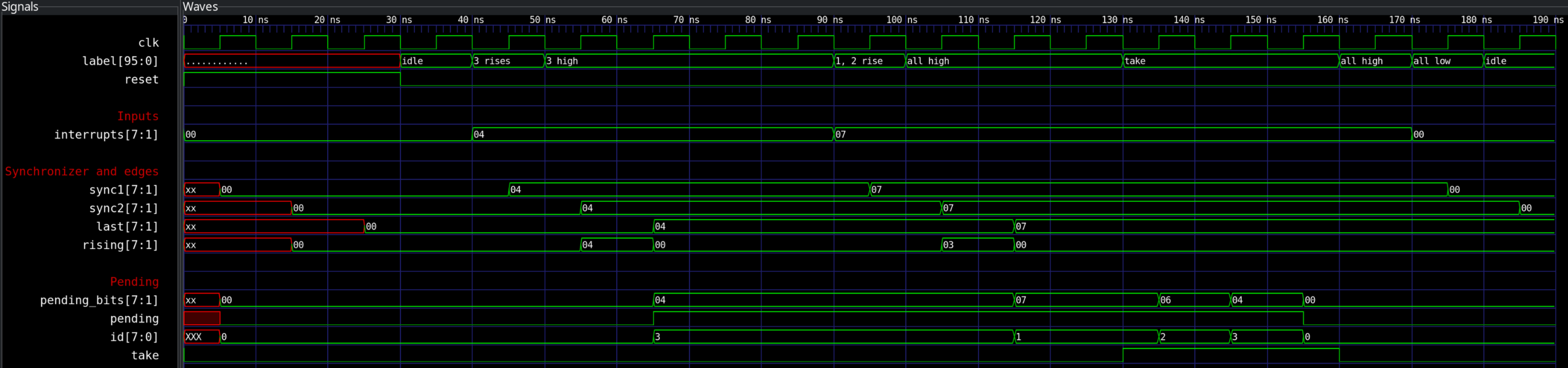
Here you can see the interrupt controller. The testbench applies a new case at every falling edge, and the outputs are what the CPU would see during that cycle.
- Input 3 goes high and stays high. It goes through the two flip-flops of the synchronizer, and three cycles later the rising edge makes interrupt 3 pending. It stays high after that, but that does not make it pending again.
- Inputs 1 and 2 go high together, while 3 is still pending. Now 1, 2 and 3 are all pending, and the lowest one, 1, is the one the CPU would take.
- The CPU takes an interrupt in three cycles in a row: each time, the lowest pending one is cleared, so the number goes from 1 to 2 to 3, and then nothing is pending anymore.
Next steps
With interrupts, the CPU can now run every instruction, and it is correct with memories that answer whenever they like. Next up are the L1 caches, after which we are technically done with the CPU itself, and can start on the rest of the memory parts of the FPGC like the SDRAM controller.