CPU part 12 - Multiply and divide
There are two seemingly simple arithmetic operations that are challenging to implement in hardware: multiplication and division. In contrast to addition and subtraction, they require more complex circuits and usually cannot be performed in a single clock cycle. This blog post will explain how they work and what ended up in the B32P4 CPU.
The operations
The FPGC has several slightly different operations for multiplying and dividing (the full table is on the instruction set page). They use the same instruction formats as the ALU operations, with either a register or a constant as the second operand:
| Group | Operations | Result |
|---|---|---|
| Multiply | mults, multu | the low 32 bits of the product (the same for signed and unsigned) |
mulshi, multuhi | the high 32 bits of the product, signed or unsigned | |
multfp | a fixed-point multiply: bits 47 to 16 of the signed product | |
| Divide | divs, divu | the quotient, rounded toward zero |
mods, modu | the remainder, with the sign of the dividend | |
divfp | a fixed-point divide: (a × 2^16) / b |
You can ignore the fixed-point operations for now, as I will probably write a separate post about fixed point math.
How a multiplier works
Multiplying in binary
Multiplying binary numbers is done like this. Here is 13 × 11 as an example:
        1 1 0 1   (13 in decimal)
      × 1 0 1 1   (11 in decimal)
      ---------
        1 1 0 1   (1101 × 1, shifted 0 places)
      1 1 0 1 .   (1101 × 1, shifted 1 place)
    0 0 0 0 . .   (1101 × 0, shifted 2 places)
+ 1 1 0 1 . . .   (1101 × 1, shifted 3 places)
---------------
  1 0 0 0 1 1 1 1   (143 in decimal)
As you can see this is a quite sequential calculation if you were to calculate it this way from top to bottom. However, the middle rows are independent of each other allowing for parallelism, but when you start using 32 bit numbers this starts to use a lot of resources.
Options in hardware
There are roughly three ways to do this in hardware for 32-bit numbers:
| Option | How it works | Speed | Size |
|---|---|---|---|
| Shift-and-add | one adder, which adds one row per cycle | 32 cycles | tiny |
| A full multiplier | all rows at once, added by a tree of adders | could be one long cycle, or several pipelined shorter cycles | large |
| A hardware multiplier block | a full multiplier that is already built into the FPGA | depends on how you use it | free as these are baked into the FPGA |
Shift-and-add is what you would build on a smaller FPGA without multiplier blocks, or what CPUs do in software when there is no hardware for this operation (like many microcontrollers).
Modern CPUs use a full multiplier, made as fast as possible with several optimization tricks, disproportionally complex to implement in FPGA logic compared to the rest of the B32P4 CPU.
Hardware multipliers in an FPGA
Building a full multiplier from the normal logic of an FPGA would take a lot of it, and would be slow. That is why FPGAs have special blocks for it. You can think of it similarly like the M9K memory blocks: technically you could create your own SRAM in FPGA logic, but it would be slow and take huga amounts of resources. In the Cyclone IV that I use, they are called embedded multipliers, and there are 116 of them. Each one can do one 18 × 18-bit multiply, or two 9 × 9-bit multiplies, and treats its inputs as signed or unsigned. Newer Altera FPGAs (Cyclone V and up) call them DSP blocks: those can also multiply wider numbers and have adders built in, so they can for example add up a few products by themselves.
Each embedded multiplier also has its own optional registers: one on each input, and one on the output. These matter a lot for the speed. A register inside the block sits right next to the multiplier, while a register in the normal logic of the FPGA can only be reached through the routing between them, which takes time. This is also where I had a lot of trouble in the past. You want to make sure that Quartus (the software that build the FPGA design from the Verilog HDL) optimally places the 18 × 18 multipliers and their registers to allow for 32 bit multiplies. So while technically you could just write y = a x b in Verilog, you need to be a lot more explicit to get proper timings. And because we use two 18 × 18 blocks for each half of the multiply, you preferably want to use two clock cycles for the full 32-bit multiply. In the earlier CPU designs I made, I did not properly understand this and this caused the multiply operation to be often the timing bottleneck in my design. That is also why I am going a bit more in depth in this blog post.
The B32P4 multiplier
Two stages
A full 32-bit multiply does not fit in one cycle, but the work splits nicely in two halves, which line up with EX and MEM:
                  EX                    │                     MEM
                                        │
             ┌──► ah × bh ──► register ─┼─┐
             ├──► ah × bl ──► register ─┼─┤
  a, b ──────┤                          │ ├──► add the four parts ──► pick the bits ──► result
             ├──► al × bh ──► register ─┼─┤
             └──► al × bl ──► register ─┼─┘
                                        │
In EX, the four embedded multipliers do their part, and the results go into the registers at the end of the cycle. Those are exactly the output registers of the blocks: the multiplies are followed directly by a register, with only a clock enable, so Quartus moves them into the blocks. In MEM, normal logic adds the four parts together, and picks the bits of the result: the low half, the high half, or bits 47 to 16 for multfp.
In the resulting implementation in my CPU design, the four multipliers do not have any input registers. This is due to our forwarding logic in EX. This means that timings could be improved even further by first registering the inputs to the multipliers at the cost of an extra cycle for the entire multiply operation, which would introduce a new stall which I do not like. I am choosing not to do this now, and only do this if needed later (which I hope is not the case, as this is already much better than what I did previously).
A new multiply every cycle
Because the register between EX and MEM works like a pipeline register, the two halves of the multiplier can work on two different multiplies: while one multiply is adding its parts in MEM, the next one can already do its four multiplies in EX. So a new multiply can start every cycle. One of the new things in B32P4 is this pipelined multiplier: in the previous FPGC versions a multiply waited in EX for several cycles, which is simpler, but it holds up the whole pipeline for every multiply. A program that does a lot of multiplies, like software 3d rendering, can now do one every cycle as long as they do not depend on each other.
The result only exists at the end of MEM, which makes a multiply a late result, just like a read from memory. An instruction that needs the result right away waits one cycle in ID, and then gets it from WB:
cycle           0   1   2   3   4   5   6   7
mults r1 r2 r3  IF  ID  EX  MEM WB
mults r1 r1 r4      IF  ID  EX  MEM WB
add r3 r4 r5            IF  ID  ID  EX  MEM WB
The second mults starts right behind the first one, and only the add, which needs r4 right away, waits a cycle. There is no new kind of hazard here: it is the same late-result stall that was already there for reads.
How a divider works
Why division is even harder
Division is a different story. There are no divider blocks in the FPGA, and dividing cannot be split up the way multiplying can as there is almost no way to parallelize it. In a division, each step depends on the result of the step before it, as you will see below. That makes it hard to do many steps at once.
Long division in binary
Division is the reverse of multiplication. A multiply adds shifted copies of a number, and a divide subtracts shifted copies of the divisor, as long as they fit. You start with the divisor shifted as far to the left as it goes, and work your way down to no shift at all. Each time the shifted divisor fits in what is left of the dividend, you subtract it, and the quotient gets a 1 at that place. When it does not fit, the quotient gets a 0 there.
Here is 13 / 3 with 4-bit numbers:
start with:           1 1 0 1   (13)
3 shifted 3 places: 1 1 0 0 0   (24)  does not fit in 13  quotient bit 3 = 0
3 shifted 2 places:   1 1 0 0   (12)  fits: 13 - 12 = 1   quotient bit 2 = 1
3 shifted 1 place:      1 1 0   (6)   does not fit in 1   quotient bit 1 = 0
3 shifted 0 places:       1 1   (3)   does not fit in 1   quotient bit 0 = 0
So the quotient is 0100, which is 4, and 1 is left: the remainder. Indeed, 4 × 3 + 1 = 13.
Binary makes this simpler than long division in school: the divisor either fits once or not at all, so there is no guessing how many times it fits. Each step is just a compare and a subtraction. But you can also see why the steps cannot be done at the same time, like the rows of a multiplication: 6 would fit in 13, but it does not fit in the 1 that is left after subtracting 12. Each step needs what is left after the step before it. For 32-bit numbers this takes 32 steps, one for each bit of the quotient.
In hardware, the divider turns the shifting around. Instead of shifting the divisor one place to the right each step, it shifts what is left one place to the left, and brings in the next bit of the dividend at the bottom. Then it can always compare with the divisor itself. That comes down to the same thing, but the compare and the subtraction always happen at the same place, so they only need to be 32 bits wide.
Options in hardware
There are a lot more ways to divide than to multiply:
| Option | How it works | Pros | Cons |
|---|---|---|---|
| In software | no divide instruction: the compiler calls a function that does long division with normal instructions | no hardware at all | very slow (lots of microcontrollers do this) |
| Restoring division | the long division above, one bit per cycle: always subtract the divisor, and when the result is negative, it did not fit, so add the divisor back (restore it) | small, simple, and easy to follow | 32 cycles, and a step that has to restore needs a subtraction and an addition |
| Non-restoring division | one bit per cycle as well, but it never restores: when the result is negative, it keeps it, and adds the divisor in the next step instead of subtracting it | every step is a single addition or subtraction, so each step is faster | also 32 cycles, and the remainder can end up negative, so it needs a correction at the end |
| Higher radix (SRT) | 2 or more quotient bits per cycle, using a small lookup table to guess the next bits | 2 to 4 times faster | more logic, harder to get the timing right, and hard to get correct: the Pentium FDIV bug in 1994 was a few missing entries in such a table |
| Newton-Raphson | compute 1/b with a few rounds of multiplies, each round doubling the number of correct bits, and then multiply by a | very fast with good multipliers, used in many FPUs and GPUs | complex, using floating points, needs a table to start from, and an extra step to get an exact integer result and remainder |
On top of each option, a divider can skip the leading zeros of the dividend, so dividing small numbers takes fewer steps.
What is in B32P4
I chose to implement the restoring division, mostly because that was the option I found the most example code of online. I currently do not skip the leading zeros, so every divide takes the full number of steps. If I start doing division heavy workloads (probably software 3d rendering), then I might add that in later.
Two cases need a bit of care:
- Division by zero does not stop the CPU, but gives a defined result: all ones for the quotient, and the dividend for the remainder (the same rule RISC-V uses). That is exactly what the long division gives by itself: zero always fits, so every quotient bit becomes 1, and nothing is ever subtracted from the dividend. The divider only has to make sure it does not give the all-ones quotient a sign.
divfpdivides a × 2^16, which is a 48-bit number. The divider does that by simply doing 16 more steps, in which the next bit is always a 0, so adivfptakes 48 steps.
Waiting in EX
A divide starts the divider in its first cycle in EX, and then waits there until the divider is done. While it waits, EX is busy, so the instructions behind it wait too, and MEM gets bubbles, just like when a read waits in MEM in the previous post. Once the divider is done, the divide moves on to MEM and takes its result with it.
cycle            0   1   2   ...  34  35  36  37  38
divu r5 r2 r6    ID  EX  EX  ...  EX  MEM WB
add r6 r2 r7     IF  ID  ID  ...  ID  ID  EX  MEM WB
The divu spends 34 cycles in EX: one to start the divider, 32 for the steps, and one with the result. The result of the divide goes through the same path as the result of a multiply, so it is a late result too, and the add that needs it waits one more cycle in ID. I could have sent the result through the ALU instead, to save that cycle, but the path through the ALU is the tightest one in the whole CPU, and one cycle does not matter next to the 34 the divide already takes.
The divider must start exactly once for each divide. That sounds obvious, but a divide can also be in EX while a later stage is busy, for example behind a read that waits for memory. Then the divide is still in its “first cycle” in EX for a while. So the CPU remembers that the divider has started, and forgets that when the divide leaves EX.
Simulation
Let’s look at the multiplier and the divider in a simulation.
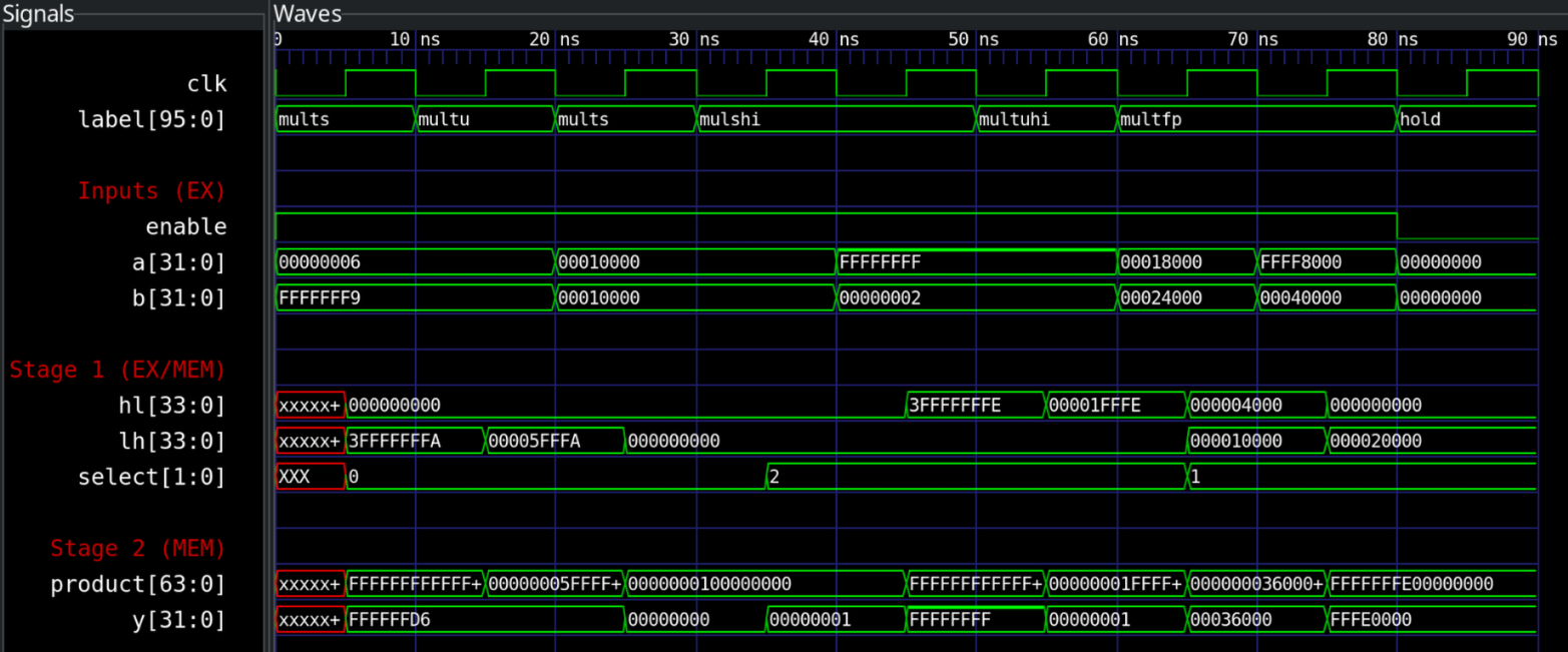
Here you can see the multiplier with a new multiply in every cycle. The testbench gives the operands as EX would, and the four parts appear after the rising edge, where MEM adds them up.
multsandmultuof 6 and -7 give the same low word:FFFFFFD6, which is -42.- 0x10000 × 0x10000 is 2^32, so the low word is 0 and the high word (
mulshi) is 1. - -1 × 2 is -2: the signed high word is all ones, but for
multuhi,FFFFFFFF× 2 is1FFFFFFFE, so its high word is 1. - The two
multfpcases are 1.5 × 2.25 = 3.375 (00036000) and -0.5 × 4 = -2 (FFFE0000). - In the last cycle, the multiplier does not take new operands, so the result stays.
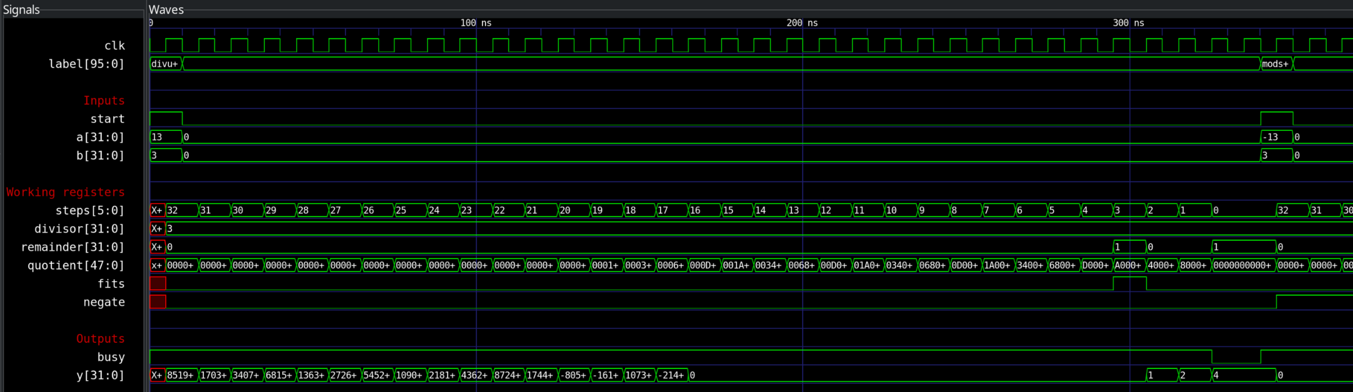
Here you can see the divider doing 13 / 3 from the example above.
- The first 28 steps bring in the zeros at the top of the dividend, so nothing happens.
- In the last 4 steps you can see the quotient bits 0, 1, 0, 0 come in at the bottom, so the result builds up as 0, 1, 2, 4. Only in the second of those steps does the divisor fit.
- At the end, 1 is left: the remainder.
- Busy is 1 from the start until the result is there.
- Afterwards a new instruction starts.
Next steps
With multiply and divide, the CPU can now run every instruction that does a calculation. The one big thing that is still missing before the caches are interrupts, so that is most likely what we will go into next.